Tuesday, November 29, 2016

A plethora of new stuff from Yarmouth Model Works

A few new things to let you know about.
All are new etched items on the Yarmouth Model Works website.
First up a 40' Morton running board and brake step;
I've revisited the running board and lateral braces with a new etching ;
The big one is 6 different arrangements of Carmer Cut levers. The first 5 are for specific PRR cars, while the last one is a more generic application. On the Carmer Cut lever webpage there are 2 downloadable documents which will greatly assist you in deciding which levers to purchase. I hope you're as excited by these as I am;


 And lastly, we've revisited our brake lever etching. We've made them a little "sleeker" as well as adding a little tab for hooking that bit of chain onto. And we're offering more on a fret;
The website is now fully updated with the exception of the brake levers, which should be done later today. Have a look, tell your friends, and email me should you have any questions.


Sunday, November 27, 2016

St Thomas Freight House Part III

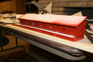
So we've been flinging paint and sticking down shingles.
The walls got a coat of Scalecoat CNR Red #11. The roof and the back got a coat of coach green, and the platform top was given a coat of Floquil Foundation.
The Foundation was allowed to cure for a couple of days.


With the Foundation well cured, out came the oil colours. The first pass was with Burnt Umber. The intensity was varied as it was applied along the platform. I just use a piece of styrene as a palette and splash some Turpenoid onto it. With the brush a drag a little colour into the Turpenoid and make a kind of a wash. The key here is to vary the intensity and not to overwork the paint. Let that dry.
Then a pass was made with Burnt Sienna. The idea is to get a variety of browns happening. The transparency of the oils is working to our advantage here.
The last pass was with Lamp Black. I'm going to let that dry and look at it again in a couple of days. I can come back and add more browns and/or black if  I wish. But for now I'm satisfied.
I had spent a whole day the previous day applying Builders in Scale shingles. Turns out I had more in my stash than I had first thought, but sadly not quite enough. There's about 3/8" at the top missing shingles. Good thing I ordered more last week.

So for now, we're calling it done. I can now add ground cover around the base and think about other yard structures.
This was a fun little project and it's kinda got me thinking about the station proper.


This guy will be a tad more challenging. Bunting or no bunting.


Friday, November 25, 2016

Where's Waldo II

We've all done it.
It's part of the reality of building models.
One little part swan dives out of the tweezers and heads for the floor.
Isn't it astounding how far a tiny piece of metal, plastic or resin can bounce?
How many hours, over the years have we spent crawling around in the dust and crud looking for that part we just spent 30 minutes cleaning up?
And when we're down there, isn't it fun when you find the part you gave up on a week ago?
At any rate, I was installing sill steps on a Funaro & Carmelengo kit for a client, when the 4th and last sill step took the swan dive.
Down onto the floor I go, thinking this'll be easy. The part is black, the floor is grey and it was recently vacuumed.
Full denial!
I was about to go back into the stash of leftover bits when I looked at the underside of the model.
Can't decide whether to be pleased or annoyed.
But it is time to call it a day.

I'm not sure what his point is...

No doubt it's purely coincidental, but twice this past week I've gotten emails from people asking technical questions. Now I'm quite happy to share my limited knowledge with anyone who asked, in the interests of growth and improvement.
But this one has me wondering;

Message:
Are your kits made of resin?

If so, what do you recommend other than the cyanoacralates for assembly as cyanoacralates are highly hydrophylic and can, therefore, be wedged apart by wedging from accumulated moisture as well as having a very high coefficient of thermal expansion, which also can result in their joints debonding (place a joint in a freezer overnight).

Cyanoacralates are **not** a true adhesive as they merely displace the air in a joint and rely on the partial vacuum they thusly create with respect to atmospheric pressure -- there is no no adhesive ionic or covalent bonding when using cyanoacralates.  Such is why they have a greater tensile strength and a much lower sheer strength.  Consequently, US Navy and NASA forbid using cyanoacralates for ocean, rocketry, and orbital engineering.

Model sailing ships in museums, even those in enclosed cases, have had the knots in rigging, fixed with cyanoacralates, fracture from repeated slight temperature variations resulting in cyclic fatigue (much like repeated bending of a wire coat hanger until it fractures).
 
 
Now I'm in no position to argue the science in this fellows assertions, but I don't know that I care. CA works just fine for me and I have 30 year old resin kits that are holding up just fine.
I'm more curious as to why this fellow felt the need to present this data to me in this manner. Is he just showing off? Does he somehow feel better having demonstrated a superior knowledge about some arcane subject. Or is he fishing for an obscure reason not to purchase kits from me?
For some reason, this feels a bit like on line trolling to me. Sadly having 2 websites and a blog leaves me open to this kind of email and I knew it going in, but really? 

Thursday, November 24, 2016

The St Thomas Freight House Part II

So we left off with the beginnings of the building shell.
I cut 5 internal bulkheads to match the ends, to which the back and the roof will be secured to.
A back was cut and glued in place. The height of the back piece is 5/8" taller than the sides so as to cover the back side of the plywood base.


The roof piece was carefully cut with the 2 long edges having a bevel to match the roof pitch. It was a simple matter of carefully making multiple passes with the knife held at the right angle guided by a long straight edge.
A little bit of fascia trim was added from scale 2"x8" strip, as well as a few triangular braces under the eaves to insure that the overhang can't sag.
The back side was puttied to hide any seams, since it's right at the aisle. It will be painted to match the fascia when that time comes.
And now it's time for paint! The building gets a coat of CNR Red #11. When this has cured, the platform will get painted to represent creosoted timbers. The roof and the backside will get a coat of CNR green. The roof gets this as an undercoat for the peel and stick shingles I have on order, and as far as I can tell the shingles were green.
And the backside gets that green since that's the planned fascia colour.
I have to wait a couple of days now for the paint to fully cure before the next colours get applied. Then we can look at how I'm going to finish the platform decks


Sunday, November 20, 2016

The St Thomas Freight House, Part I

At the end of Hiawatha St, there was a classic Grand Trunk designed freight house that stood for almost a century.
 Into the later part of the 20th century it was certainly looking worse for wear, but in the era I model it was an important structure and was well cared for.
The location on the layout for this structure only allows for about 1/3rd of the width due to choices I made, but I will copy it's full 140' length. Over the next couple of blog posts I will share how I built this structure.
I chose to build this model mostly from styrene.  I like working with this material. It's quick and easy. Scribe and snap. A little solvent cement and we're off. There's a large variety of siding styles available, along with shapes for trim pieces, etc.
As the structure is meant to be in good repair grain should not be visible in an HO scale model. If you don't agree, have a good look at photos of wooden buildings and freight cars. Grain is only visible in planks that are due for repair or replacement.

I started by creating a basic drawing. I used photos to help me determine door and window locations. I adjusted the window sizes to match Tichy castings that I felt looked close.
The locations of the doors and windows was transferred onto a piece of 0.060" thick styrene. And the pieces were numbered to ensure that everything goes back together in the same order.
All the lines are scribed and then snapped, with the window and door "plus" discarded.
Using the 4' level as a "fence" the pieces are reassembled and glued together with solvent cement. This is left to cure fully for at least a few hours.
Board and batten siding is then applied over the core. Again glued in place with solvent cement. The liquid is flowed all around the edges and in through all the door and window openings. This is weighted down and allowed to fully cure.
Working from the backside all the door and window openings are cut through the board and batten siding. The openings are checked against the castings and the battens are trimmed to clear the casing trim of the window.
The windows are glued in. The door openings are trimmed with jambs and casing. And freight doors are added, which were cut from basic scribed siding.
The 2 sides were created using the same techniques.
The 2 sides are now glued to the front, with lots of steel blocks in play to keep things square. The front wall is a tad bowed right now but we'll fix that as we go along.
At this point the dock/floor is needed. I cut a piece of 5/8" ply to a dimension of 2 3/4" x 19 7/8". The perimeter was wrapped with some scribed siding and the top is decked with the same material. All this is secured in place with Lepage's No More Nails. A great product which joins these dissimilar materials very well.
We'll leave the project at this point while the deck fully cures. There's a roof to create, internal bulkheads for bracing and support and trim bits. And then paint!
Stay tuned!


Sunday, November 13, 2016

Decoder swap

Yesterday a few friends came over to help out with a large project.
Replacing the QSI decoders in the F-7 fleet with Loksound sound decoders.
Photos and details can be seen here on Trevor's blog, http://themodelrailwayshow.com/cn1950s/?p=7708. Why repeat what he's said?
But I will take a moment to talk further about why I decided to go to this trouble.
While there are people out there who really love QSI decoders and the features they come with, my experience has been less than stellar.
I have found the QSI products a royal pain to program. They use a goofy extended address format that pretty much demands the use of their proprietary programmer. Which is fine, but the trials I went through to first get a programmer and then get the damn thing to work was nothing short of rage inducing. The owner of QSI couldn't figure out how to get the drivers to work on my pc, while my "Nerds On Site" guy figured it out in 2 minutes.
The actual software I found to be clunky and firmly rooted in DOS era.
The clincher was watching my friend Bob Fallowfield program a new decoder  for me. The sound files are software and loaded onto the decoders. So updates are easy. Improvements to controls and sounds can be made by loading new software. No more replacing chipsets or whole decoders when technology moves forward.
And then there's the actual sounds. The first time I heard a Loksound decoder I was hooked. The diesels sound like what I have heard. The prime movers rev up and then the loco moves, like it's supposed to. And nice and throaty!
And then there's Matt Herman. The Loksound guy in North America. Any company who offers such congenial and helpful customer service that Matt brings gets my money in a heart beat. You can meet Matt at many of the train shows across North America over the course of the year. He gets what we want from our models and works hard to take care of the rare problems. That all companies behaved this way.
Now it's back to the bench, as not all the units got done yesterday. And then there's all the programming. But I'm actually looking forward to that task.

Tuesday, November 8, 2016

You'll laugh when you see it

I was poking around on Goggle satellite, looking at the town of Delhi, as I plan how I'm going to model that town. I've had a rethink on that part of the layout and some exciting options are presenting themselves. More on that later.
Have a good look at this image and let me know when you find it.
It's nice to see that even in today's world the tech is not perfect.
If you're really stymied cheat and look here.
I chuckled for a bit


Friday, November 4, 2016

All better now!

Aylmer is now without short circuits.
I cut my losses and removed the entire bus and started hunting for the shorts from there.
Turns out I had 3 major issues.
One turnout had a sliver of copper not cut through which I found by passing a file over the suspect turnout.
3 turnouts all had the same issue. The feeders for the stock rails were pinched under the pc board ties and as a result were shorting out. Easy enough to fix once discovered.
The 3rd issue is really the main cause of the first 2. I was a bit of a dumbass. I should have checked every turnout as I built them to make sure the pc ties were fully cut. And I should have been checking the trackwork as it was being laid.
I could have saved myself a few hours of creative swearing and the cost a few Insulation Displacement Connectors. (Which, by the way, I'm in love with!)
Aw well. Lesson learned. Won't make that mistake again.
On to fresh tragedies.

Now I can wire in the frog juicers and run the cable for the UT-5s and I can test the track.